Post by Rick CPost by pozzPost by Rick CPost by pozzPost by Rick CPost by pozzPost by pozzThe critical installations often have cables that gives mains power
(230Vac) to coils, for example relays or door ring bell.
People use 230VAC for _doorbells_?!?! Are they trying to wake the dead?
Here in the US doorbells are usually 16VAC, though 24VAC is also used.
I've also seen 10VAC and 12VAC mentioned, but I think that's uncommon.
They are very common here (for example [1]). 230Vac is the common mains
voltage so the doorbells are connected to mains, through a momentary
switch out of the door.
[1] https://comenzielectrice.ro/pdf/Bticino%20-%20Matix%20Catalog.pdf
Search for AM5048
I don't know about where you live, but doorbells in the US are powered from low voltage, so they don't require all the safety precautions.
So you have a dedicated power supply for doorbells?
LOL, when you say "dedicated power supply", you mean this.
https://www.amazon.com/HQRP-Transformer-Compatible-8v-16v-24v-Replacement/dp/B094DKV9NQ
The price on this link is 23 euros, I think a 230Vac doorbell costs less.
Yeah, Amazon is often the highest price for various items. The transformer is as little as $8 in local stores.
Post by pozzPost by Rick CThe high voltage side of the transformer is mounted on a proper high voltage box. The rest of the wiring is low voltage, so requires no particular safety precautions. The power is low, so even at the low voltage the wire is not heavy, typically 20 or 22 gauge.
Here they usually route the doorbell 230Vac cables together with other
cable of electrical system (lightning...) using the same junction boxes.
"Routing" typically needs no boxes. You still need a box for the button and for the bell. I'm sure you are not grasping the simplicity of a low voltage doorbell.
I don't want to defend installations that THEY do here where I live. I'm
just describing what usually happens.
In the apartment there are already "in-wall" tubes and junction boxes
for mains distribution and frames for lights switches. In this case, I
think it's worth it to "waste" one module to install a 230Vac buzzer
inside and one module to install a 230Vac pushbutton to activate the
buzzer outside. During installation of mains circuits you already have
230Vac cables and you can use them for doorbell too.
The prices of 230Vac and 12Vac doorbells are similar (see [1] and [2]),
with the plus you can avoid an additional power supply/transformer, even
if it is cheap.
Post by Rick CPost by pozzPost by Rick CPost by pozzHere 99% of house
doorbells are 230Vac. The installation is much more easy, because you
use directly the mains cables without additional hw.
Doesn't the button require a much more substantial mounting, as well as the bell itself? That's what the low voltage is avoiding. I think my transformer is mounted in the pantry ceiling not unlike a lightbulb (which is also in the pantry ceiling).
See [1]. That is a 3-modules frame that can be installed in the wall.
It's already compatible with 230Vac push-buttons. With one of this you
can have the push-button for an outdoor lamp, a push-button for the
doorbell and a keytag reader for anti-burglar system (for example).
Is it for outdoor use??? The only items I found were the 12V power supply.
Sorry for misunderstanding. It isn't for outdoor use, it is usually
installed "out of the door" of the apartment, but inside a
multi-apartment building.
Of course, in isolated building where the doorbell switch is really
outdoor, you can't use that.
Post by Rick CPost by pozzYou don't need an additional substantial mounting dedicated for doorbell
pushbutton.
I have no idea what you are describing. No one I've ever known has high voltage light switches mounted next to the front door with or without a bell button. In fact, it's not allowed to mix low voltage and high voltage in the same box.
When the apartment is one of many in a building (condominium), there's
usually a public light on the common part of the floor (balcony?
landing?) inside the building. And you could want to switch on when you
are outside your apartment. Both the light button and doorbell button
are 230Vac, so no mixing.
Post by Rick CPost by pozzPost by Rick CPost by pozzThe pushbutton that activates the doorbells are a normal button (but
momentary) that could be used to activate lights in the room.
I don't know what that means "normal". Here, all wiring junctions or terminations must be done in an approved box.
Yes, of course. The same box used for a switch that turns on a light.
There's no need to add a dedicated box for doorbell.
You keep saying that, but you have to put in an unsightly and obtrusive high voltage box, next to your front door. If you want to put other high voltage switches in that, fine, but it doesn't change the need for the high voltage box for the doorbell button.
I don't think this[3] is worse than this[4]. Of course, it depends on
personal taste.
Post by Rick CPost by pozzPost by Rick Chttp://youtu.be/6GUODvOVz10
The wire junctions shown here are valid, but not common in the US. Mostly people are used to "wire nuts", which are like this, and work well.
https://www.cableorganizer.com/categories/electrical-supplies/cable-termination/tan-wire-connector/
The mistake that is often made when using them, is to not twist the wires together before twisting the nut on. The nut is not intended to be a mechanical connection, just electrical. So the insulated portion of the wire should be twisted together first.
Post by pozzPost by Rick CA device on a high voltage circuit has to be mounted on a box or has to be a box rated for such wiring. A door bell uses much simpler wiring and needs no special boxes or precautions. I have seen no small number of doorbell buttons mounted directly in the door frame, having been drilled out to 1/2 inch for mounting the button.
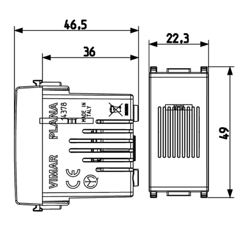
In the past, the doorbells were dedicated box mounted on the wall, near
the door, inside the apartment.
Now they tend to install as a module inside push-button frames that are
"inside" the wall ([1] just as an example).
Anyway my board is not near the buzzer, but could be near the pushbutton
that activates the buzzer.
[1]
https://www.rmelectric.it/3054-large_default/ronzatore-vimar-plana-230v-bianco-suoneria-campanello-segnalatore-acustico-14378.jpg
The bell itself is not an issue. The PITA is the button.
https://www.amazon.com/doorbell-push-button/s?k=doorbell+push+button
These are much easier to mount where they are most convenient. See the small button with the screw terminals? Below is a crude video of a similar button showing the minimal requirements for installation. This guy is upgrading to a video doorbell.
https://www.google.com/search?q=round+doorbell+button+mounting&client=firefox-b-1-d&sxsrf=APwXEdfIYgYKthf4KothWTYEIfsvEMSPHg:1683555901893&source=lnms&tbm=vid&sa=X&ved=2ahUKEwj2l_e79uX-AhXaMVkFHVUuBuUQ0pQJegQIMBAG&biw=923&bih=497&dpr=1.94#fpstate=ive&vld=cid:1132e9ee,vid:N0H1jSUySH0
Much simpler and less expensive than running high voltage wiring to the button.
If you have only a doorbell pushbutton outdoor, yes it could be simpler.
However here usually installs a "normal" in-the-wall 3-modules box, so
you can have multiples commodities: doorbell push-button, button for a
light and so on. This box is already compatible for 230Vac signals.
Post by Rick CI'm wondering if your doorbell has the low voltage transformer inside and the wire to your doorbell is also low voltage? It just makes zero sense to run high voltage to the button.
[1] https://i.ebayimg.com/images/g/1q0AAOSw7Wtd4lsd/s-l1600.png
Why do you keep showing pictures of indoor switches? This has nothing to do with the outside doorbell button.
See above for the misunderstanding.
Post by Rick CI did find this in your catalog.
bronze bell 12 Va.c. - 5 VA - 80 dB
Yes, I never said there aren't low voltage buzzers, but they aren't
frequently used here.
[1] https://amzn.eu/d/8iPOXgt
[2] https://amzn.eu/d/b31Lcre
[3] https://i.ebayimg.com/images/g/1q0AAOSw7Wtd4lsd/s-l1600.png
[4]
Loading Image...